Engineered for reliability and 99% availability. Specified to IEC standards. Supplied and installed by field-experienced engineers with documented commissioning on every project.
PRODUCT CATEGORY 01
We supply and install medium voltage switchgear panels for primary distribution substations in commercial, industrial, and utility applications. All equipment is specified to IEC 62271 and verified against site fault level calculations prior to procurement.
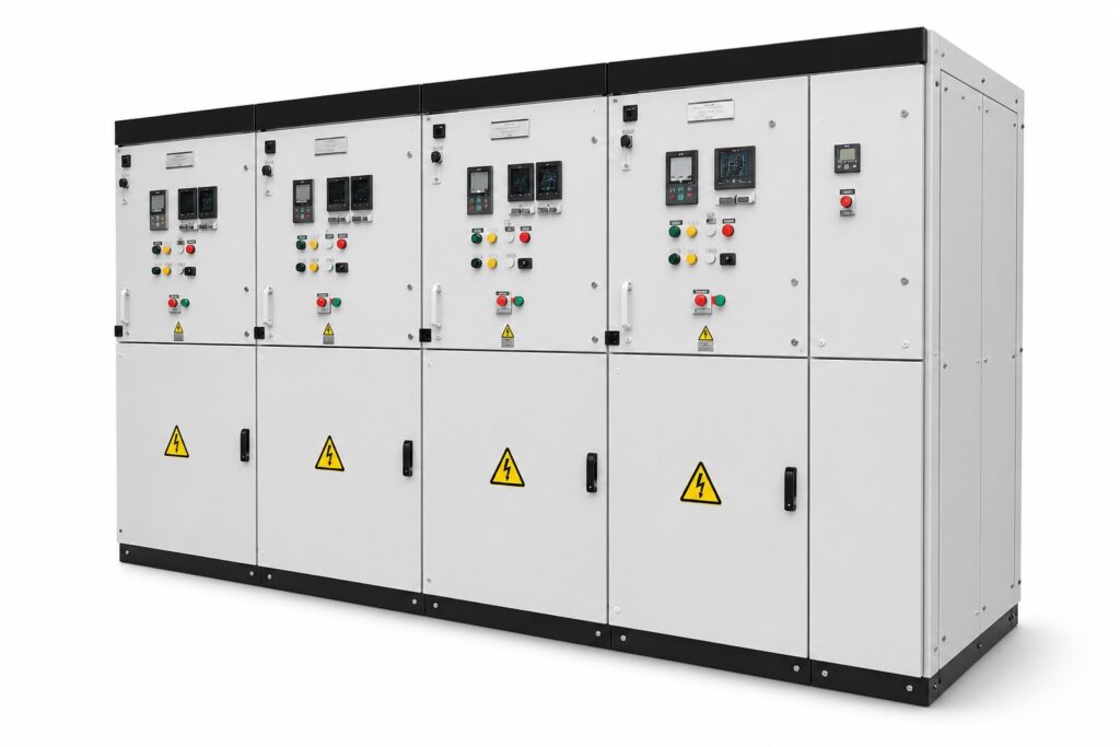
Fully-compartmentalized metal-clad panels for primary distribution substations. Specified for 15kV, and 30kV systems. Internal arc classification available where required by site risk assessment.
SF6 and vacuum-insulated RMUs for ring and radial feeder configurations. All protection elements undergo secondary injection testing at commissioning. Suitable for compact urban substation footprints.
VCB panels for MV switchboards with mechanical endurance testing and contact resistance measurement verified at site acceptance. Spare parts documentation and operational manuals included as standard.
Overcurrent, earth fault, differential, and distance protection relays configured and tested to the protection coordination study. IED configuration files and test records supplied at handover.
| Voltage Range | 15kV – 30kV |
| Busbar Rating | Up to 2500A |
| Fault Level | Up to 40kA (1 second) |
| Protection Functions | ANSI 50/51, 67, 87, 21 |
| Communication Protocol | IEC 61850 / Modbus RTU/TCP |
| Applicable Standard | IEC 62271-100 / IEC 62271-200 |
| Customization | Yes — project-specific design |
PRODUCT CATEGORY 02
Low voltage switchboards designed to IEC 61439-1 and -2, with full type-test documentation. We supply main distribution boards, sub-distribution boards, motor control centers, and power factor correction panels for new builds and retrofit projects.
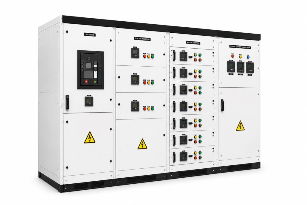
LV MDBs for transformer secondary distribution. Rated per IEC 61439-2. Bus-coupler configurations available for critical facilities requiring N+1 redundancy. Metering to MID
Floor-level distribution boards for commercial and industrial tenant distribution. Short-circuit and protective device coordination calculations provided as a design deliverable on every project.
Fixed and draw-out MCCs with DOL, soft-starter, and variable frequency drive (VFD) configurations. Full loop testing and interlock verification performed at commissioning.
Automatic capacitor bank panels sized from site load profile data. Harmonic-filtered variants (detuned reactors) available for non-linear load environments to prevent resonance.
| Voltage | 400V / 415V, 3-phase, 50Hz |
| Busbar Rating | Up to 6300A |
| Short-Circuit Rating | Up to 100kA peak |
| Protection Form | Form 2b to Form 4b (IEC 61439) |
| Metering | Multifunction meter / MID accuracy class |
| Applicable Standard | IEC 61439-1, IEC 61439-2 |
| Type Test Documentation | Full type test records provided |
PRODUCT CATEGORY 03
We supply distribution transformers from verified manufacturers with full factory test reports (FTR). Transformer sizing is calculated from site load schedules. All units are commissioned with insulation resistance, turns ratio, and magnetizing current tests prior to energization.
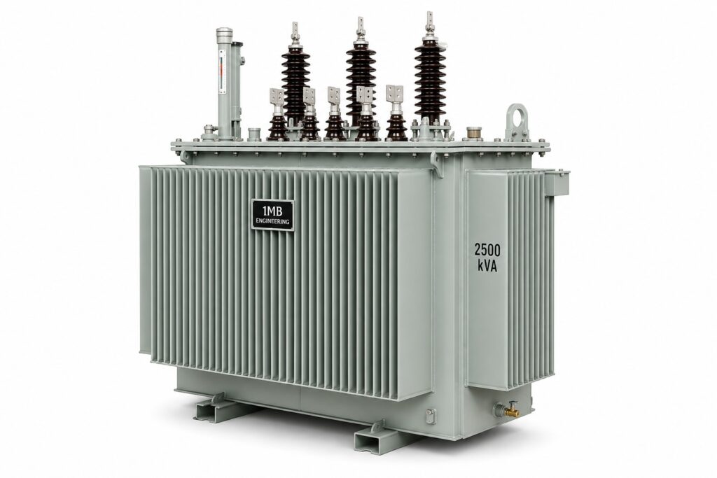
ONAN/ONAF cooled distribution transformers from 25kVA to 2500kVA. Equipped with OILTAP or de-energized tap changers. Full factory test report mandatory on all units prior to dispatch acceptance.
Cast resin and VPI dry-type transformers for indoor installations, data centers, and environments where oil is operationally or safety-prohibited. Available in Class F and Class H insulation systems.
Packaged MV/LV substation units combining RMU, transformer, and LV switchboard in a single factory-assembled enclosure. Factory acceptance tested prior to site delivery, reducing site installation time.
HV/LV earthing grids designed to IEEE 80 and IEC 60364. Earth resistance testing and step/touch potential verification included as commissioning deliverables.
| Capacity Range | 25kVA – 2500kVA |
| Primary Voltage | 15kV – 30kV |
| Secondary Voltage | 400V / 415V |
| Vector Group | Dyn11, Ynyn0, Dzn0 |
| Cooling Type | ONAN, ONAF, AN, AF |
| Applicable Standard | IEC 60076-1 to IEC 60076-5 |
| Test Reports | Full FTR mandatory on every unit |
PRODUCT CATEGORY 04
Protection relay selection, configuration, and coordination are executed by our protection engineers using site-specific short-circuit studies. All settings are verified by secondary injection testing prior to system energization. No protection system is handed over without a documented test record.
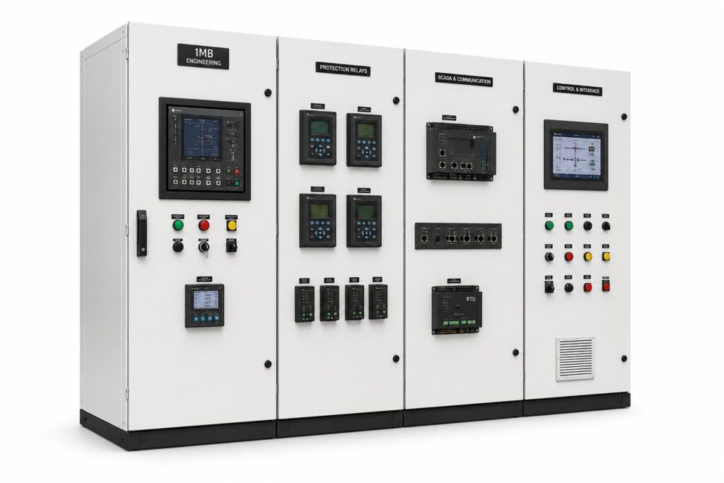
Overcurrent (ANSI 50/51), earth fault (50N/51N), differential (87T/87B), distance (21), and auto-reclose relays. Settings documented in relay coordination reports and verified against protection study requirements.
IEC 61850 GOOSE messaging, DNP3, and Modbus RTU/TCP integration for remote monitoring and control systems. Signal lists and SCADA interface documentation supplied at project handover.
Bus coupler, bus section, and generator interlock schemes with hard-wired and PLC-based logic. Loop testing and factory acceptance testing (FAT) included as a standard project deliverable.
Protection coordination studies produced to IEC 60255 and IEEE C37.112. Settings verified by independent secondary injection testing prior to energization and system handover.
| Relay Type | Numerical / IED-based (microprocessor) |
| Protection Functions | ANSI 50/51, 67, 87, 21, 81 |
| Communication Protocol | IEC 61850, DNP3, Modbus |
| Testing Equipment | Secondary injection |
| Applicable Standard | IEC 60255, IEEE C37.112 |
| Documentation | Coordination study + test records |
Reliable power isn’t one machine — it’s a system that thinks. At every facility, three coordinated technologies make sure the lights never blink: a precision Automatic Voltage Regulator inside every generator, an intelligent Automatic Transfer Switch that swaps sources in seconds, and a Generator Synchronizer that makes two engines behave as one. Here is what we engineered, and why it matters.
Sensitive equipment doesn’t fail because the power goes off — it fails because the voltage wobbles. The Automatic Voltage Regulator is the quiet guardian inside each 300 kVA generator that refuses to let that happen.
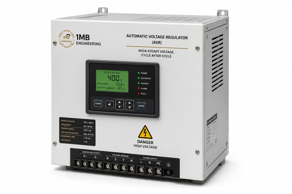
Built into the brushless Leroy Somer alternator (model TAL-046-F), the Leroy Somer R150 AVR continuously measures the generator’s output and instantly adjusts the excitation field to hold the voltage exactly where it should be. Whether the port load is light overnight or surging as cranes and pumps kick in, the output stays locked at 230/400 V with a regulation accuracy of just ±1%.
| Alternator | Brushless, single bearing, 4-pole |
| Excitation System | Self-excited |
| Nominal Voltage / Frequency | 230/400 V · 50 Hz |
| Voltage Regulation | ±1% |
| Harmonic Coefficient (THF) | < 2.5% |
| Insulation Class | Class H — 125/40 °C continuous |
Voltage instability quietly killing your equipment? 1MB Engineering specifies and tunes AVR-controlled generation that holds voltage to ±1%.
When the utility drops, every second of darkness is a second of lost productivity — and at a working port, a safety risk. The Automatic Transfer Switch is the decision-maker that watches both power sources around the clock and moves the load to whichever one is healthy, automatically.
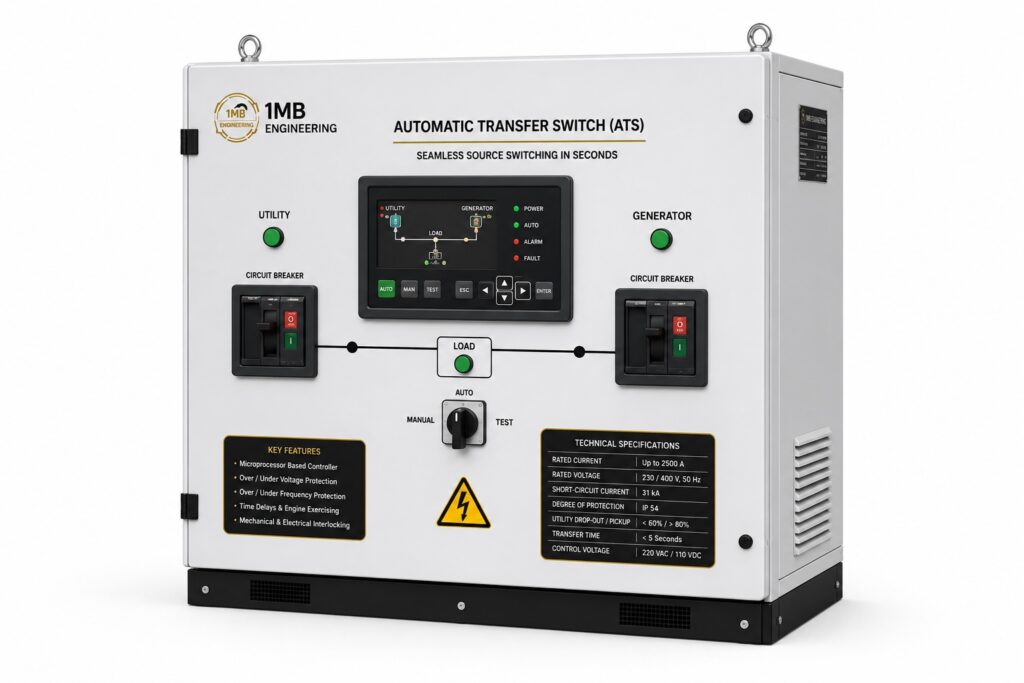
A microprocessor-based controller constantly monitors the voltage and frequency of both the utility supply and the standby generators. The moment the primary source drops below threshold, the ATS commands the generators to start, waits until their output is stable and within tolerance, then transfers the load through two motorized 1200 A air circuit breakers. When the grid returns, it transfers back — all governed by adjustable timers so the switching is smooth, not jarring.
| Rated Current | Up to 2500 A |
| Rated Voltage / Frequency | 230/400 V · 50 Hz |
| Circuit Breakers | Two (2) motorized ACBs up to 2500 A |
| Short-Circuit Current | 31 kA |
| Degree of Protection | IP 54 |
| Main Controller | Self-acting intelligent device (microprocessor-based) |
| Utility Drop-out / Pickup | < 60% drop-out · > 80% pickup |
| Timers | Gen start 2–1500 s · Warm-up 5 s · Re-transfer 15 s · Cool-down 60 s |
| Interlocking | Mechanical + Electrical |
| Contacts | Silver Alloy |
Can your facility survive a grid outage without a flicker? We design ATS-controlled changeover systems that transfer load in seconds, fully interlocked and tested.
Running two generators is easy. Running them together — in perfect electrical lockstep — is engineering. At the facilities we serve, both gensets are paralleled by an automatic synchronizer that matches voltage, frequency, and phase before they ever touch the busbar, and intelligently sheds the second engine when it isn’t needed.
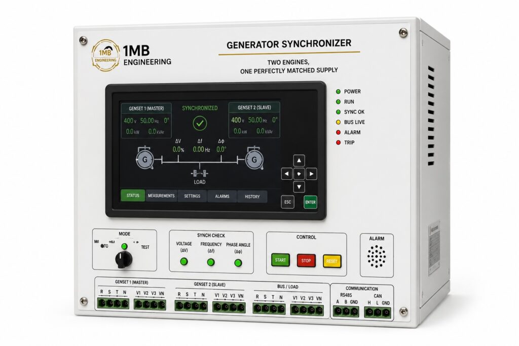
When the mains fails, both generators start and the synchronizer brings the incoming machine into exact agreement with the busbar. Working with the engines’ electronic speed governors, it fine-tunes speed and phase, then closes the breaker only when voltage, phase, and frequency match within tolerance for half a second. The result is a connection with no shock, no surge, and no stress on the equipment.
| Maximum Voltage | 660 V |
| Voltage Range | 70–110% |
| Frequency Range | 45–65 Hz |
| Frequency Difference | 0.15 Hz |
| Closing (Phase) Angle | 60–90° adjustable (±6° to ±9° window) |
| Voltage Difference | 10–15% |
| Synchronization Time | < 5 seconds |
| Contact Rating | 400 V AC / 8 A · 35 V DC / 8 A |
| Consumption | 4 VA at nominal voltage |
| Configuration | Two (2) gensets, master/slave auto load-sharing |
Paralleling generators — or burning fuel running engines you don’t need? We design auto-synchronizing, load-managed generation that scales to demand.
The AVR keeps each generator’s output clean and stable. The synchronizer makes two generators act as one. The ATS decides, in seconds, which source feeds the port. Individually they are components — together they are uninterrupted, intelligent power. That is the standard 1MB Engineering Consult delivers.
Equipment selection, sizing calculations, protection coordination, and commissioning are delivered as an integrated service — not as separate procurement and engineering engagements.
Adding {{itemName}} to cart
Added {{itemName}} to cart